
Testing
Summary
As there are many requirements for the design of the conveyer system for this project, there are also many ways to test if these requirements were met. The main objective to get out of this project is a functioning conveyer belt that successfully moves carbon fiber from the outlet of the shredder to the inlet of the oven. This is the biggest test of all, but some other things that were tested on the conveyer system are the speed, torque, and how straight the belt tracks. To test these things, a variety of methods were used. The speed of the conveyer was measured by making a small mark on the belt, allowing the conveyer to run for one minute and measuring how far the mark on the conveyer had travelled. The distance was measured with a ruler or a measuring tape. It should travel 1 foot in one minute per the requirements of the design. Torque was also tested due to a motor failure. Torque was tested by measuring the perpendicular force on the shaft to rotate the pulley and move the belt. Another thing that was tested was how straight the belt tracked when it was ran for 3 minutes at a time. This was done by running the conveyor for three minutes and measuring how far off to one side the belt was tracking. From here, adjustments were made via tensioner to attempt to get the belt to track the other way. Other adjustments that were made to ensure straight tracking was the squareness and parallellism of the frame.
One issue that was faced during testing occurred right before conducting speed testing. Right before colleting speed testing data, the conveyor started making a loud noise and then stopped transmitting torque. After some investigation, it was found that this was due to a gear tooth within the motor being sheared off. This happened due to the torque needed to move the belt being greater than the torque capacity the motor was rated for. This issue progressed over a few weeks but was eventually solved by replacing the motor with one that has higher torque capabilities and ran off higher voltage. The new motor was wired up and mounted into the conveyor design and speed testing was able to be conducted smoothly.
Test 1: Torque Test
To the right is a collage highlighting the materials needed and the set up required for torque testing:
-
The image on the left is a top view of the lathe chuck holding onto the shaft which is then clamped to a moment arm (scrap aluminum). On the left of the moment arm, there is a hook that can be better seen in the picture in the top right.
-
The picture in the top right is an isometric view of the torque testing set up. The hook/scale is easily seen here. This scale is used to measure the perpendicular force needed to rotate the shaft and move the conveyor.
-
The picture shown in the bottom right is a visual of all the materials needed to conduct the torque testing.


Figure 4.1. Torque Test Materials and Setup Collage
Test 2: Speed Test
To the right in figure 17 is an image of the original motor used for the conveyance design. It can be seen that some teeth sheared off of the small gear causing the motor to stop transmitting torque from the motor to the shaft. The first attempt at the speed test was a fail. This fail is what prompted the torque test to explain why the motor failed.
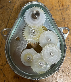
Figure 4.2. Failed Motor - Broken Gear Teeth
Figure 18 shows the set up for speed testing. It highlights the starting and ending points of the test (the wood shims) and how the distance was measured via ruler. The aluminum scrap was the item used to track the movement of the belt. A timer was used to time how long it took for the test item to move 1 ft. The target speed was 1 ft/min.

Figure 4.3. Speed testing in action
Test 3: Belt Tracking Test
Figure 19 shows the severity of the initial results when attempting belt tracking testing. The belt was tracking so far to the right that it would sometimes start rubbing on the frame. With adjustments to the tensioner and the frame structure, the belt tracking was controlled.

Figure 4.4. - Belt tracking test run
Testing Video Library


