
Analysis
Summary
The first step in analyzing this system was to determine just how much space is available inside the oven to work with. This required thermodynamics as well as some electrical engineering knowledge. A lot of the latter analyses were structural type analyses which included free body diagrams, statics, mechanics of materials, and material science to determine forces, stresses, and material types & sizes. Since this structure also has moving components, technical dynamics equations were also useful in calculating the speed of the conveyer.
Requirements
-
Conveyer can move material at 1ft/minute.
-
Rollers must not deflect more than ¼ inch under the load of the carbon fiber composite
-
Motor must supply a minimum Torque value of 2 lb.-in.
-
Shaft must not deflect more than 5° in torsional deformation.
-
Conveyor must be at least 2 feet in length to span from shredder to oven.
-
Bearings must be able to support 1 batch of carbon fiber composite.
-
Bearings must also be able to support 3 lb. rollers
-
Conveyor may not weigh more than 20 lbs.
-
Conveyer must transport 1 wing trimming in batches.
-
Device will run every thirty minutes for 2 minutes.
-
Belt must be able to withstand at least 2 lb.-in. of tension.
-
Belt must track straight within 3 cm in either direction
Analysis 1: Volume of Oven / Space for Conveyer
The requirement for this is that the volume of one wing tip and the conveyer system can fit inside the oven. The first analysis was done to determine the volume of the inside of the oven enclosure that is available for the conveyer and material to take up. This was done by rearranging the voltage equation to find the resistance. This resistance was then used to find the actual power of the oven. Using this power value and by rearranging the thermal energy equation (in appendix A01), the volume of the oven was found. The volume of the oven and the space allowed for the conveyer came out to be 1.14 m3. This analysis allowed for confirmation that the conveyer system would fit inside the oven enclosure.

Figure 2.1. Analysis 1
Analysis 2: Mass of 1 Carbon Fiber Wing Trimming (1 batch)
The second analysis was simple but very important to the completion of the project. It included calculating the mass of one carbon fiber wing tip. Only one wing tip was calculated because the JCATI team decided that with the batch system, one wing tip will go through the process at a time. By converting units and rearranging the density equation, the mass of one wing tip was 13.81 lb. These calculations can be found in appendix A02. This will be used in a latter structural analysis as a distributed load to ensure the frame of the conveyer can support the material being moved. This analysis helped aid latter structural analysis using the weight of the conveyer as well as the conveyer.
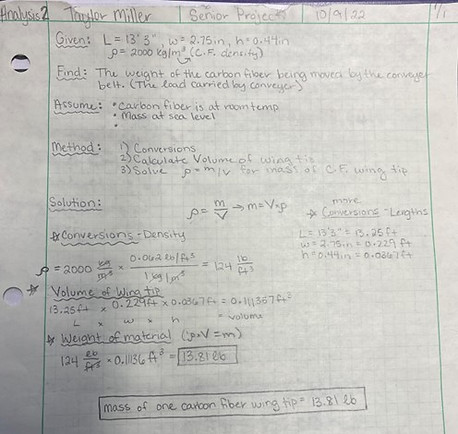
Figure 2.2. Analysis 2
Analysis 3: Length of Distributed Load on Conveyer
The requirement for this is that one wing trimming must fit the length of the oven. The third analysis was also simple but necessary to determine whether the one-wing-trimming-per-batch idea was plausible with the current oven dimensions. This analysis focused on finding the length of the conveyer that one wing trimming will take up to ensure that the length of the oven could hold the volume of material coming in. Finding this length also led to an analysis that combines analysis 2 and 3 and using the weight of the material and the length of it along the conveyer as a distributed load. This length was found to be 15.41 inches or 1.28 ft. (see appendix A03). The oven is larger than this, so this analysis confirmed that the design of the oven and conveyer system would match up.

Figure 2.3. Analysis 3
Analysis 4: Support Reactions of Leg Supports
The requirement for this analysis was that the conveyer legs must be able to hold the 13.81 lb. load of material as well as a 20 lb. conveyer system. The analysis for this included finding the reaction values of the leg supports using a FBD and equilibrium equations. It was found that each leg must have reactions of about 17 lb. to support the system. This will aid in a latter analysis of using a safety factor of 3. Documentation for this analysis is located in appendix A04 of the proposal

Figure 2.4. Analysis 4
Analysis 5: Pulley Tension / Torque on Shaft
The requirement for this analysis is that the conveyer must be able to move the mass of 1 wing trimming from the shredder to the oven. This analysis focused on finding the allowable working tension of the conveyer. This involved solving for the tension to move the empty belt, tension to move the load horizontally, effective tension, and slack side tension. From these, it was found that the total tension was 1.86 lb. This allowed for a torque calculation of 0.155 ft-lb which aided in the next analysis. The design parameter here is a 2-inch pulley that was used for calculations due lack of availability of smaller diameters. Documentation for this analysis can be found in appendix B08 of the proposal


Figure 2.5. Analysis 5
Figure 2.6. Analysis 5 Continued
Analysis 6: Required RPM / HP
Expanding on analysis 5, this analysis focused on finding the necessary RPM of a 2 -inch pulley to move the belt the required 1 ft/min. Using the conveyer belt target speed (1ft/min) and the circumference of the rollers, the required RPM came out to be 1.91 or roughly 2 RPM. This allowed for the required power from the motor to be calculated. An alternate solution for HP was also included to confirm the initial solution was correct. The design parameter for this is that a motor that supplies at least this much HP. Which was not hard to find. A speed reducer will likely be needed. This motor can be found in the Appendix B09.

Figure 2.7. Analysis 6
Analysis 7: Deflection Across Rollers
The requirement that this analysis stemmed from was that the rollers of the conveyer must deflect less than ¼ inch under the load of the carbon fiber. The analysis involved free body diagrams, equilibrium equations, bending stress equations, shear force calculations, and beam deflection formulas. The beam deflection for the roller was calculated to be 5.28x10^-6 in., which is less than ¼ inch and meets requirements. The design parameter that came from this analysis was the confirmation that the 6-inch roller will suffice in ensuring there is a deflection of less than ¼ in. The documentation for this analysis can be found in Appendix B13.


Figure 2.8. Analysis 7
Figure 2.9. Analysis 7 Continued
Analysis 8: Column Analysis
The requirement that inspired this analysis is that the leg supports must be able to support the weight of one carbon fiber wing trimming as well as the weight of the 20 lb conveyer with a safety factor of 2. The analysis for this requirement involved doing a column analysis on one leg support. Johnson’s equation was rearranged to solve for the maximum length a 2x2 steel column that can support the 67.62 design load. This resulted in a design parameter of a leg support less than 115 inches. The documentation for this analysis can be found in Appendix B11.

Figure 2.10. - Analysis 8
Analysis 9: Minimum Required Key Length
The requirement that inspired this analysis is that the shaft must be able to withstand a Torque value of 2 lb.-in. The analysis for this included solving for the minimum required key length for shear and shear stress on the key. The key transmits torque between the shaft and the pulley and needs to be a minimum length to withstand the Torque. This was done by solving for shear force, design shear stress, minimum required length of key, and actual shearing stress, respectively. This resulted in a minimum key length of 0.00165 inches. A practical key length greater than this value will be chosen. Documentation for this analysis can be found as a drawing of the key in Appendix B12.

Figure 2.11. Analysis 9
Analysis 10: Torsional Deformation in Shaft
The requirement that inspired this analysis is that the shaft must not deflect more than 5° in torsional deformation. This analysis involved using the torque and polar moment of inertia of the shaft to solve for max shear stress. The max shear stress was calculated to be 9.47 psi. Then, torsional deformation was then found to be 0.00078°, which is much less than the 5° requirement. The design parameter that resulted from this analysis was a 1-inch shaft that was needed to fit inside the 2-inch diameter pulley. Documentation for this shaft can be found in Appendix B10 of the proposal.

Figure 2.12. - Analysis 10
Analysis 11: Belt Length
The requirement that involved this analysis was the need for the conveyor to be at least 2 feet in length. With this in mind, a center-to-center distance between the pulley and last idler roller was designed to be 2 feet, meaning that half of the last roller and pulley extend beyond this. Analysis 11 in Appendix A11 shows that ½ the circumference of both the end roller and pulley is added to the 2 feet on top and bottom of the conveyor. The total belt length for the device was calculated to be 4.52 ft. A standard belt size of 6 ft was chosen that is adjustable via hammer-on, hook-style applications. Documentation for this design parameter can be found in Appendix B14, a drawing of the belt being purchased from McMaster-Carr.

Figure 2.13. Analysis 11
Analysis 12: Dynamic Load of Bearing
The requirement for this analysis is that the bearings must be able to support the load of one batch of carbon fiber composite (13.81 lb.) as well as the 3 lb. roller. This analysis started off with finding the design life of the bearing, assuming 5,000 hours of use. The design life was calculated to be 600,000. This was then used to find the basic dynamic load rating which was 14.18 lb. To prove that the bearing size chosen (0.25”) would be sufficient for its purpose on the conveyor, the calculated value was compared to McMaster-Carr which indicated that the dynamic load rating for the bearing chosen was 200 lb. This is much more than 14.18 lb., so this indicates that the design parameter of using a 0.25” bore diameter bearing for the conveyor design is more than strong enough to support the load it is under. Documentation for this can be found as a drawing of the mounted ball bearing in Appendix B07.
