
Construction
Summary
A variety of construction/manufacturing methods were used during the assembly of the Fiber Conveyance System. All components of the assembly were either purchased from McMaster-Carr or manufactured in the machine shop at CWU. The vertical bandsaw was used to cut key stock to length, the horizontal band saw was used to cut shafts to length, and keyways were machined using a key broach and collar. When manufacturing the frame, three different manufacturing methods were used: The sheet metal was cut using a shear, the holes were punched on a flat pattern using a sheet metal turret punch, then it was bent into a C-channel using a break, power shears were then used to cut out material to allow for clearance around a gear box cover for the shredder.

Figure 3.1. Straight Shaft & Straight Pulley assembly
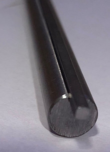
Figure 3.4. Key and keyed shaft assembly

Figure 3.2. Keys cut with vertical bandsaw

Figure 3.5. Broaching a keyway in a pulley

Figure 3.3. Straight Shaft/Pulley Assembly (top view)
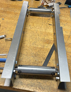
Figure 3.6. Frame/ Drive Pulley/ Idler roller/ Bearing Assembly

Figure 3.7. Frame Flat Pattern & completed C-channel Frame
Figure 3.1 shows the assembly of the straight shaft and the straight pulley in an isometric view. Figure 3.3 shows this same assembly but from the top view. This small sub-assembly was manufactured by using 1/2" raw round stock from CWU machine shop and cutting it to 14" lengths using the vertical bandsaw. Then, the shaft was inserted into the bore of the pulley, and it was complete.
Figure 3.2 is an image of 4 keys that were cut from 1/8" square key stock from CWU. Each key was cut to be 2" in length using the vertical bandsaw and Sawzall. In figure 3.4, one of the keys is shown assembled within the keyway of the keyed shaft that drives the pulley.
Figure 3.5 shows an image of a keyway being broached in a straight pulley so that torque can be transmitted from the shaft to the pulley. This is done with a broach, broach collar, shim, and a hydraulic press. The hydraulic press uses force to push the broach down and remove material in the shape of a keyway. A video of this process can be found below in the "Construction Video Library."
Figure 3.6 is a photo of the frame assembled with 4 bearings, one idler pulley, and one driver pulley.
Figure 3.7 features the two sides of the frame. The top frame has holes punched and is bent into a C-channel. The bottom frame in the picture is the flat pattern with all the markings used to make cuts and bends. The holes were punched using a sheet metal turret punch. A video of this can be found below in the "Construction Video Library."

Figure 3.8. Drawing Tree
Construction Video Library


Construction Video Library
The video gallery demonstrates the manufacturing methods used to create the parts featured in figures 3.5 and 3.7 above. See above for descriptions of each method and the resources used in each process.